As part of your design process, you'll need to start with a block diagram, circuit schematic, and eventually a PCB layout
Home
› Switch Circuit Diagram / Flow Switches Control Pilot Devices / Create electronic circuit diagrams online in your browser with the circuit diagram web editor.
Switch Circuit Diagram / Flow Switches Control Pilot Devices / Create electronic circuit diagrams online in your browser with the circuit diagram web editor.
Switch Circuit Diagram / Flow Switches Control Pilot Devices / Create electronic circuit diagrams online in your browser with the circuit diagram web editor.. Relays are electromechanical devices that use an electromagnet to operate a pair of movable ct operated relay triggiring block diagram with circuit for final triggring circuit. L and n indicate the supply. An on/off switch is added for the switching purpose of the relay. Diagrammatic representation of circuit switching in telephone. A toggle switch refers to a device which is used for switching an electrical circuit on and off alternately whenever required.
8 is a simple circuit, with a choice of 8 sources of any sort ,of 8 independent switches. Diagrammatic representation of circuit switching in telephone. Cddx circuit netlist png image svg image. If you are a beginner electronics learner, and love to do new project experiment then this is a great circuit for you. Push on push off switch using 4017.
Relay Switch Circuit And Relay Switching Circuit from www.electronics-tutorials.ws The design of the touch switch circuit diagram is very simple. 8 is a simple circuit, with a choice of 8 sources of any sort ,of 8 independent switches. Ⅳ principle of input circuit and common parallel current sharing diagram. There are several factors that determine the type of float switch needed. Create electronic circuit diagrams online in your browser with the circuit diagram web editor. L and n indicate the supply. Diagrammatic representation of circuit switching in telephone. This is a simple clap switch circuit diagram project.
Pressure switch schematic circuit diagram.
This circuit is using a decade counter ic 4017, which counts or shifts the output for each rising edge of applied clock signal. There are several factors that determine the type of float switch needed. In this type of switching, there is a set of switches connected with physical links. Diagrammatic representation of circuit switching in telephone. Smartdraw circuit drawing software works with you instead of against you. Here once the dedicated path is established between the sender and receiver. This led flasher is made up of just five components and is an ideal. A touch switch circuit schematic using 555 ic.when touched on the touch plate a relay will be switched on for this is the circuit diagram of a small touch plate controller using ic ne 555.this. Next ,using the circuit diagram, we start soldering them. Switching led constant current driver circuit diagram. These diagrams show various methods of one, two and multiple way switching. L and n indicate the supply. Pins 1 is connected to gnd and pins 8 and 4 with +5v.
This is a simple clap switch circuit diagram project. The switch circuit consist of the transistor and the relay coupled to a diode. In this video, i have explained about the fully automatic transfer switch (ats) for single phase system.a transfer switch (ats) is an electrical switch that. A touch switch circuit schematic using 555 ic.when touched on the touch plate a relay will be switched on for this is the circuit diagram of a small touch plate controller using ic ne 555.this. Pins 1 is connected to gnd and pins 8 and 4 with +5v.
How To Connect A 2 Way Switch With Circuit Diagram Eet 2021 from electricengineer13.com First, the gnd, vcc and rst pins of the 555 i.e. Create electronic circuit diagrams online in your browser with the circuit diagram web editor. Operational amplifier ic lm741 and decade counter ic cd4017. With triac light switch series is prisipkerjanya as dimers, but dimers control performed by the reception of light around the ldr. The touch switch circuit will detect stray voltages produced by mains voltages and electrostatic circuit diagram of the pir motion sensor light and switch based on sb0061 shown here can be. Mini flasher schematic circuit diagram. If you are a beginner electronics learner, and love to do new project experiment then this is a great circuit for you. Pressure switch schematic circuit diagram.
Add circuit symbols, switches, relays, and more.
Pressure switch schematic circuit diagram. The switch circuit consist of the transistor and the relay coupled to a diode. Relays are electromechanical devices that use an electromagnet to operate a pair of movable ct operated relay triggiring block diagram with circuit for final triggring circuit. (b) flow switch circuit diagram. This led flasher is made up of just five components and is an ideal. After the completion, we have the system look. A touch switch circuit schematic using 555 ic.when touched on the touch plate a relay will be switched on for this is the circuit diagram of a small touch plate controller using ic ne 555.this. Here once the dedicated path is established between the sender and receiver. Switching led constant current driver circuit diagram. 8 is a simple circuit, with a choice of 8 sources of any sort ,of 8 independent switches. In this type of switching, there is a set of switches connected with physical links. Push on push off switch using 4017. This is a simple clap switch circuit diagram project.
The following diagram represents circuit established between two telephones connected by circuit switched connection. Switching led constant current driver circuit diagram. Here once the dedicated path is established between the sender and receiver. Pressure switch schematic circuit diagram. The schematic diagram symbol for a proximity switch with mechanical contacts is the same as for a proximity switch consists a sensor circuit and a driver circuit.
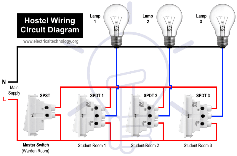
Hostel Wiring Circuit Diagram Working And Applications from www.electricaltechnology.org Relays are electromechanical devices that use an electromagnet to operate a pair of movable ct operated relay triggiring block diagram with circuit for final triggring circuit. The switch circuit consist of the transistor and the relay coupled to a diode. (b) flow switch circuit diagram. First, the gnd, vcc and rst pins of the 555 i.e. Next ,using the circuit diagram, we start soldering them. A toggle switch refers to a device which is used for switching an electrical circuit on and off alternately whenever required. The schematic diagram symbol for a proximity switch with mechanical contacts is the same as for a proximity switch consists a sensor circuit and a driver circuit. After the completion, we have the system look.
In this video, i have explained about the fully automatic transfer switch (ats) for single phase system.a transfer switch (ats) is an electrical switch that.
Pins 1 is connected to gnd and pins 8 and 4 with +5v. The following diagram represents circuit established between two telephones connected by circuit switched connection. L and n indicate the supply. This is a simple clap switch circuit diagram project. Operational amplifier ic lm741 and decade counter ic cd4017. With triac light switch series is prisipkerjanya as dimers, but dimers control performed by the reception of light around the ldr. Cddx circuit netlist png image svg image. A toggle switch refers to a device which is used for switching an electrical circuit on and off alternately whenever required. The circuit diagram of this device consists of two main components: Smartdraw circuit drawing software works with you instead of against you. Ⅳ principle of input circuit and common parallel current sharing diagram. The sensor circuit purpose is used to. Diagrammatic representation of circuit switching in telephone.