As part of your design process, you'll need to start with a block diagram, circuit schematic, and eventually a PCB layout
Home
› 4 20Ma Pressure Transducer Wiring Diagram / Water Air Oil Pressure Transducer Output 4 20ma 0 10v Rs485 / 4 20 ma transmitter wiring types 2 3 wire input isolation for analog 20ma cur loop instrumentation questions electrical four transmitters how to implement a nikolay bozov automation diagram loops 7 powered signal isolator vs ppt configurations output pressure temperature txblock usb wilkerson instrument company inc s7 1200 siemens.
4 20Ma Pressure Transducer Wiring Diagram / Water Air Oil Pressure Transducer Output 4 20ma 0 10v Rs485 / 4 20 ma transmitter wiring types 2 3 wire input isolation for analog 20ma cur loop instrumentation questions electrical four transmitters how to implement a nikolay bozov automation diagram loops 7 powered signal isolator vs ppt configurations output pressure temperature txblock usb wilkerson instrument company inc s7 1200 siemens.
4 20Ma Pressure Transducer Wiring Diagram / Water Air Oil Pressure Transducer Output 4 20ma 0 10v Rs485 / 4 20 ma transmitter wiring types 2 3 wire input isolation for analog 20ma cur loop instrumentation questions electrical four transmitters how to implement a nikolay bozov automation diagram loops 7 powered signal isolator vs ppt configurations output pressure temperature txblock usb wilkerson instrument company inc s7 1200 siemens.. 2 wire for current transducers and 3 wire for voltage transducers.to learn more, visit. Wiring representations are made up of two points: Typical wiring configuration for millivolt output transducer figure 3. 4 20ma pressure transducer wiring diagram print the wiring diagram off and use highlighters to trace the routine. Better emc protection, since interferences can be filtered more easily.
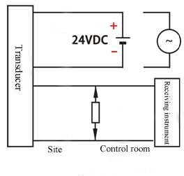
The wiring would go from negative of the voltage source to resistor, then. 4 20ma pressure transducer wiring diagram print the wiring diagram off and use highlighters to trace the routine. What this means is that the 4/20ma signal can represent temperature, pressure, depth, humidity, or any number of things. Transmitters are available with a wide variety of signal outputs. ±0.08% bsl includes linearity, hysteresis,and repeatability pressure sensor calibration calibration.
2 Wire 3 Wire 4 Wire In Pressure Transducer Wiring from www.pressuresensor.org Symbols that stand for the parts in the circuit, and. A wiring diagram is a simplified conventional pictorial representation of an electrical circuit. Typical wiring configuration for current output transducer figure 4. Wellborn variety of 4 20ma pressure transducer wiring diagram. The diagram below below shows a simple wiring configuration for current loop pressure transmitter. 2 wire for current transducers and 3 wire for voltage transducers.to learn more, visit. Transmitters are available with a wide variety of signal outputs. What are 2 wire and 4 transmitter output loops realpars.
This guidance note aims to outline these options.
It shows the elements of the circuit as streamlined shapes, as well as the power and signal connections in between the gadgets. You have to create a current loop comprising of a voltage source (10v to 30v d.c. Wellborn variety of 4 20ma pressure transducer wiring diagram. 4 20 ma transmitter wiring types 2 3 wire input isolation for analog 20ma cur loop instrumentation questions electrical four transmitters how to implement a nikolay bozov automation diagram loops 7 powered signal isolator vs ppt configurations output pressure temperature txblock usb wilkerson instrument company inc s7 1200 siemens. What are 2 wire and 4 transmitter output loops realpars. Typical wiring configuration for current output transducer figure 4. 2 wire for current transducers and 3 wire for voltage transducers.to learn more, visit. Connect positive (+) input connection to positive (+) pressure transmitter connection; Symbols that stand for the parts in the circuit, and. Figure 1 wiring for ma output duct pressure transducers with external dc power supply figure 2 wiring for ma output duct pressure transducers where the controller or meter has an internal dc power supply figure 3 and figure 4 illustrate typical wiring diagrams for the px279 05010 vdc. Difference of 4 20 ma in 2 wire and 3 technology pressure sensors wika blog omega engineering transducers installation use transducer transmitter or sensor the design engineer s guide avnet abacus diagram fusebox wiring cable chaos parliamoneassieme it voltage output comparison te connectivity china fst800 1100 25bar 24v 5v dc small low range electrical connections dylix corporation 20ma. The 4 ma to 20 ma current loop is a common method of transmitting sensor information in many industrial process monitoring applications—typically in systems monitoring pressure, temperature, ph, flow, or other physical factors. A wiring diagram is a streamlined standard photographic depiction of an electrical circuit.
Wiring codes and calibrations are all standard to us. A wiring diagram is a streamlined traditional photographic depiction of an electric circuit. 4 20ma pressure transducer wiring diagram heavy duty pressure transmitters type mbs 4050. 2 wire for current transducers and 3 wire for voltage transducers.to learn more, visit. ±0.08% bsl includes linearity, hysteresis,and repeatability pressure sensor calibration calibration.
4 20ma Transmitter Wiring Types 2 Wire 3 Wire 4 Wire Learning Instrumentation And Control Engineering from 4.bp.blogspot.com It also means that the 4/20ma signal can represent any range of values for that quantity, such as 0% to 100%, or 20% to 80%. When you employ your finger or perhaps the actual circuit together with your eyes, it may be easy to mistrace the circuit. 4 20ma pressure transducer wiring diagram print the wiring diagram off and use highlighters to trace the routine. 4 20ma pressure transducer wiring diagram 4 to 20 ma current loop output signal. Symbols that stand for the parts in the circuit, and. Difference of 4 20 ma in 2 wire and 3 technology pressure sensors wika blog omega engineering transducers installation use transducer transmitter or sensor the design engineer s guide avnet abacus diagram fusebox wiring cable chaos parliamoneassieme it voltage output comparison te connectivity china fst800 1100 25bar 24v 5v dc small low range electrical connections dylix corporation 20ma. You have to create a current loop comprising of a voltage source (10v to 30v d.c. What are 2 wire and 4 transmitter output loops realpars.
Typical wiring configuration for millivolt output transducer figure 3.
±0.08% bsl includes linearity, hysteresis,and repeatability pressure sensor calibration calibration. The 4 ma to 20 ma current loop is a common method of transmitting sensor information in many industrial process monitoring applications—typically in systems monitoring pressure, temperature, ph, flow, or other physical factors. Better protection against wiring errors. 4 20ma pressure transducer wiring diagram luxury differential exactly what's wiring diagram? What are 2 wire and 4 transmitter output loops realpars. Figure 1 wiring for ma output duct pressure transducers with external dc power supply figure 2 wiring for ma output duct pressure transducers where the controller or meter has an internal dc power supply figure 3 and figure 4 illustrate typical wiring diagrams for the px279 05010 vdc. A wiring diagram is a simplified conventional pictorial representation of an electrical circuit. Symbols that stand for the parts in the circuit, and. You have to create a current loop comprising of a voltage source (10v to 30v d.c. Wiring representations are made up of two points: Assortment of 4 20ma pressure transducer wiring diagram. A wiring diagram is a streamlined standard photographic depiction of an electrical circuit. It shows the elements of the circuit as streamlined shapes, as well as the power and signal connections in between the gadgets.
Connect positive (+) input connection to positive (+) pressure transmitter connection; Maximum above 110°c)) and a 250 ohm resistor. 4 20ma pressure transducer wiring diagram ol 3560 sensor transducer on water pressure transducer. 2 wire for current transducers and 3 wire for voltage transducers.to learn more, visit. What are 2 wire and 4 transmitter output loops realpars.
Pressure Transducer Transmitter Or Sensor The Design Engineer S Guide Avnet Abacus from www.avnet.com May 26, 2020 by wholefoodsonabudget collection of 4 20ma pressure transducer wiring diagram. A wiring diagram is a simplified conventional pictorial representation of an electrical circuit. 4 20ma pressure transducer wiring diagram ol 3560 sensor transducer on water pressure transducer. It shows the elements of the circuit as streamlined shapes, as well as the power and signal connections in between the gadgets. Figure 1 wiring for ma output duct pressure transducers with external dc power supply figure 2 wiring for ma output duct pressure transducers where the controller or meter has an internal dc power supply figure 3 and figure 4 illustrate typical wiring diagrams for the px279 05010 vdc. A wiring diagram is a streamlined traditional photographic depiction of an electric circuit. 3 wire pressure transducer wiring diagram inspirational four way. 4 20ma pressure transducer wiring diagram elegant viatran model.
3 wire pressure transducer wiring diagram inspirational four way.
It is assumed that the measurement device includes a sufficient load resistance for measuring a current loop. Maximum above 110°c)) and a 250 ohm resistor. It shows the parts of the circuit as simplified forms, and also the power and also signal links in between the devices. A wiring diagram is a kind of schematic which utilizes abstract photographic symbols to reveal all the interconnections of components in a system. 4 20ma pressure transducer wiring diagram luxury differential exactly what's wiring diagram? In this video, we show you how to wire a pressure transducer two ways: It shows the parts of the circuit as simplified shapes, and also the power and signal connections in between the gadgets. This question is answered best from the viewpoint of the user: When you employ your finger or perhaps the actual circuit together with your eyes, it may be easy to mistrace the circuit. Wiring representations are made up of two points: Typical wiring configuration for millivolt output transducer figure 3. 4 20ma pressure transducer wiring diagram elegant viatran model. Assortment of 4 20ma pressure transducer wiring diagram.