As part of your design process, you'll need to start with a block diagram, circuit schematic, and eventually a PCB layout
Home
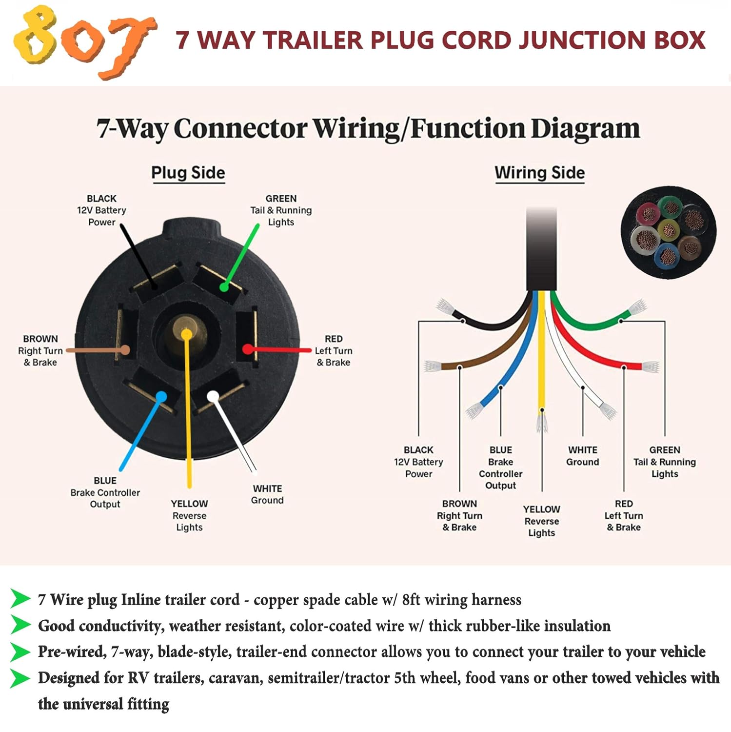
› 4 Plug Trailer Wiring Diagram : 4 Pin 7 Pin Trailer Wiring Diagram Light Plug | House Electrical Wiring Diagram - 7 way plug wiring diagram standard wiring* post purpose wire color tm park light green (+) battery feed black rt right turn/brake light brown lt left turn/brake light red s trailer electric brakes blue gd ground white a accessory yellow this is the most common (standard) wiring scheme for rv plugs and the one used by major auto manufacturers today.
4 Plug Trailer Wiring Diagram : 4 Pin 7 Pin Trailer Wiring Diagram Light Plug | House Electrical Wiring Diagram - 7 way plug wiring diagram standard wiring* post purpose wire color tm park light green (+) battery feed black rt right turn/brake light brown lt left turn/brake light red s trailer electric brakes blue gd ground white a accessory yellow this is the most common (standard) wiring scheme for rv plugs and the one used by major auto manufacturers today.
4 Plug Trailer Wiring Diagram : 4 Pin 7 Pin Trailer Wiring Diagram Light Plug | House Electrical Wiring Diagram - 7 way plug wiring diagram standard wiring* post purpose wire color tm park light green (+) battery feed black rt right turn/brake light brown lt left turn/brake light red s trailer electric brakes blue gd ground white a accessory yellow this is the most common (standard) wiring scheme for rv plugs and the one used by major auto manufacturers today.. As with something, common servicing checks may also help in keeping away from some major issues. Connect brown wire to vehicle tail light wire, yellow wire to vehicle left stop and turn wire and green wire to vehicle right stop and turn wire. A flat 4 plug for 4 wire trailers, a flat 5 plug and a round 5 plug for 5 wire trailers. The black (sometimes red) 12v and blue electric brakes wire may need to be reversed to suit the trailer. White pin for the ground.
4 pin trailer wiring diagram Below is the generic schematic of how the wiring goes. I have a 2009 ford f 150 with the 7round plug and a 4 flat wire plug i can use either one just bought a new set of magnetic lights with red and orange lens and already have the led lights mounted in the trailer only all lights work when head lights on truck are turned but no brake or turn signals i have a 7 pin to. 7 way plug wiring diagram standard wiring* post purpose wire color tm park light green (+) battery feed black rt right turn/brake light brown lt left turn/brake light red s trailer electric brakes blue gd ground white a accessory yellow this is the most common (standard) wiring scheme for rv plugs and the one used by major auto manufacturers today. Blue = electric brakes or hydraulic reverse disable (see blue wire notes below.) in the trailer wiring diagram and connector application chart below, use the first 5 pins, and ignore the rest.
How To Wire Trailer Lights 4 Way Diagram | Fuse Box And Wiring Diagram from stickerdeals.net When autocomplete results are available use up and down arrows to review and enter to select. Otherwise, the structure will not work as it should be. It should not be carrying significant loads through the trip. Blue = electric brakes or hydraulic reverse disable (see blue wire notes below.) in the trailer wiring diagram and connector application chart below, use the first 5 pins, and ignore the rest. If not, the structure will not work as it ought to be. Some trailers come with different connectors for cars and some have different wiring styles. 4 pin trailer wiring diagramtrailer plug adapter4 pin trailer connector color code 4 wire trailer plugtrailer light wiringtrailer wiring diagram7 pin to 4 pi. Trying to hook to 4 flat connector.
A flat 4 plug for 4 wire trailers, a flat 5 plug and a round 5 plug for 5 wire trailers.
Most of us aren't electricians, but that doesn't mean wiring a trailer or replacing corroded wiring is beyond us. Each part ought to be set and connected with other parts in particular manner. They can be purchased as a standalone plug for the truck or trailer, or as a complete loop with both the plug and the socket included. 6 way systems, round plug. This 4 wire boat trailer wiring diagram version is far more suitable for sophisticated trailers and rvs. There are many types of plugs used in the motorcycle trailer industry, but cars almost exclusively use a flat 4 plug. 4 pin trailer wiring diagramtrailer plug adapter4 pin trailer connector color code 4 wire trailer plugtrailer light wiringtrailer wiring diagram7 pin to 4 pi. Otherwise, the structure will not work as it should be. What do color wires go to. To connect the electric system of your trailer to the vehicle, you will be using special connector. Round 1 1/4 diameter metal connector allows 1 or 2 additional wiring and lighting functions such as back up lights, auxiliary 12v power or electric brakes. Wiring plug diagram created date: 7 way plug wiring diagram standard wiring* post purpose wire color tm park light green (+) battery feed black rt right turn/brake light brown lt left turn/brake light red s trailer electric brakes blue gd ground white a accessory yellow this is the most common (standard) wiring scheme for rv plugs and the one used by major auto manufacturers today.
I have a 2009 ford f 150 with the 7round plug and a 4 flat wire plug i can use either one just bought a new set of magnetic lights with red and orange lens and already have the led lights mounted in the trailer only all lights work when head lights on truck are turned but no brake or turn signals i have a 7 pin to. If not, the structure will not work as it ought to be. The black (sometimes red) 12v and blue electric brakes wire may need to be reversed to suit the trailer. 6 way systems, round plug. Each part ought to be set and connected with other parts in particular manner.
Pin by E w on trailer wiring diagram | Trailer light wiring, Trailer wiring diagram, Boat ... from i.pinimg.com When issues happen using the trailer, motorist might wish to know where the problem spot is located. Start by cutting the white wire and attaching it to the trailer frame. When autocomplete results are available use up and down arrows to review and enter to select. It should not be carrying significant loads through the trip. This kind of connector is great for consumer trailers. 7 way plug wiring diagram standard wiring* post purpose wire color tm park light green (+) battery feed black rt right turn/brake light brown lt left turn/brake light red s trailer electric brakes blue gd ground white a accessory yellow this is the most common (standard) wiring scheme for rv plugs and the one used by major auto manufacturers today. Trailer side car side wiring plug diagram. Below is the generic schematic of how the wiring goes.
If not, the structure will not work as it ought to be.
You will either need to find a wiring diagram for your trailer or test your wring with 12v power to verify the functions of your. The black (sometimes red) 12v and blue electric brakes wire may need to be reversed to suit the trailer. There is a really basic 4 pin trailer light wiring diagram. They can be purchased as a standalone plug for the truck or trailer, or as a complete loop with both the plug and the socket included. 6 way systems, round plug. When autocomplete results are available use up and down arrows to review and enter to select. A flat 4 plug for 4 wire trailers, a flat 5 plug and a round 5 plug for 5 wire trailers. Connect brown wire to vehicle tail light wire, yellow wire to vehicle left stop and turn wire and green wire to vehicle right stop and turn wire. When issues happen using the trailer, motorist might wish to know where the problem spot is located. As with something, common servicing checks may also help in keeping away from some major issues. Trailer wiring diagrams trailer wiring connectors. Check with a test light or vom. Below is the generic schematic of how the wiring goes.
I have on boat trailer green,white,yellow, brown with green, and brown with yellow. White pin for the ground. The pictures below show the 3 most common plugs for motorcycle trailers. You must check the trailer manual to see if the wiring is correct, but normally the white wire is called the ground wire, while the brown wire is used for tail lights. What do color wires go to.
5 Wire Trailer Light Wiring Diagram - Wiring Diagram Networks from images-na.ssl-images-amazon.com A flat 4 plug for 4 wire trailers, a flat 5 plug and a round 5 plug for 5 wire trailers. As a professional rv transporter i have seen to many trucks wired with those 2 wires to small and cause a fire from overheating. It should not be carrying significant loads through the trip. I have on boat trailer green,white,yellow, brown with green, and brown with yellow. The black (sometimes red) 12v and blue electric brakes wire may need to be reversed to suit the trailer. To connect the electric system of your trailer to the vehicle, you will be using special connector. Yellow and green are for left and right turns and braking. Above we have describes the main types of trailer wiring diagrams.
To connect the electric system of your trailer to the vehicle, you will be using special connector.
A 4 wire system will not use the 5th blue (or red) wire. This 4 wire trailer wiring diagram troubleshooting model is more acceptable for sophisticated trailers and rvs. Start by cutting the white wire and attaching it to the trailer frame. Round 1 1/4 diameter metal connector allows 1 or 2 additional wiring and lighting functions such as back up lights, auxiliary 12v power or electric brakes. When issues happen using the trailer, motorist might wish to know where the problem spot is located. White pin to your floor. Using an adapter lets you avoid having to splice into the vehicle's. • green right turn / brakes. White pin for the ground. Read convert fluorescent to led wiring diagram collection. This article shows 4 ,7 pin trailer wiring diagram connector and step how to wire a trailer harness with color code ,there are some intricacies involved in wiring a trailer. Most of us aren't electricians, but that doesn't mean wiring a trailer or replacing corroded wiring is beyond us. Check with a test light or vom.