As part of your design process, you'll need to start with a block diagram, circuit schematic, and eventually a PCB layout
Home
› What Is A Wiring Schematic - Model T Ford Forum Model T Ford Wiring Diagrams And Wire Gauges / You could be a specialist who intends to look for referrals or solve existing troubles.
What Is A Wiring Schematic - Model T Ford Forum Model T Ford Wiring Diagrams And Wire Gauges / You could be a specialist who intends to look for referrals or solve existing troubles.
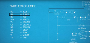
What Is A Wiring Schematic - Model T Ford Forum Model T Ford Wiring Diagrams And Wire Gauges / You could be a specialist who intends to look for referrals or solve existing troubles.. The us federal communications commission (or fcc) regulates interstate and international communications by radio and television, wire and cable, and satellite. Schematic diagrams are used to troubleshoot and install control circuits. Anyone know which wire is the signal, posative and negative. Gfci operational schematic and gfci operation. It shows how the electrical wires are interconnected and can also show where and how components are connected to the system.
The uses of these two types of diagrams are compared in table 1. A schematic shows connections in a circuit in a way that is clear and standardized. Wouldn't it be nice if you could get the full schematics, interior photos, and other technical detail before you even pick up a screwdriver? The two most commonly used are the wiring diagram and the schematic diagram. Schematic nets tell you how components are wired together in a circuit.
How To Read A Wiring Schematic Video Tips And Tricks from images.ctfassets.net It should be noted that sometimes the control functions are supplied by ac and are. Schematics are generally easier to read and understand than wiring diagrams. Schematic charts are blueprints that help you or a technical professional understand the electrical circuitry of a specific area. The electrical diagram is usually inside the appliance. Schematics are symbolic representations of complete circuits or systems created during the design phase. A wiring diagram is a simplified conventional pictorial representation of an electrical circuit. Discussion in 'electrical systems' started by mcdunk, may 28, 2006. But instead of using text to explain the recipe, a drawing is used.
It is a way of explaining how to reach a certain result.
Types of electrical diagrams or schematics. They tell you what ingredients to use and how to mix the ingredients. The uses of these two types of diagrams are compared in table 1. Schematics can be used for general information. Schematic comprehension is a pretty basic electronics skill, but there are a few things you should know before you read this tutorial. It is a way of explaining how to reach a certain result. The us federal communications commission (or fcc) regulates interstate and international communications by radio and television, wire and cable, and satellite. Some of the wiring symbols are given below which are used for showing the electrical connection between the diverse devices or machines in an. Labels, tags, marks or numbers to assist in traceability and allow for systematic troubleshooting of the design. If you are fixing, repairing, or troubleshooting an appliance, use the wiring diagram that came with your appliance to assist you to repair it. What is a solidworks electrical schematic. Terminal marking and wiring connection diagrams are helpful mainly in troubleshooting process while tracing the wires and making connection to the devices. They show the function of the circuit or system.
Schematic electrical wiring diagrams are different from other electrical wiring diagrams because they show the flow through the circuit rather than the a schematic is best described as an impression of the circuit and wiring than a genuine representation. Wouldn't it be nice if you could get the full schematics, interior photos, and other technical detail before you even pick up a screwdriver? The manuals depict the original factory placements haynes makes a manual with the wiring schematic for the o2 sensor on a 1991 chevy blazer s10. A wiring diagram or schematic is a visual representation of the connections and layout of an electrical system. Anyone know which wire is the signal, posative and negative.
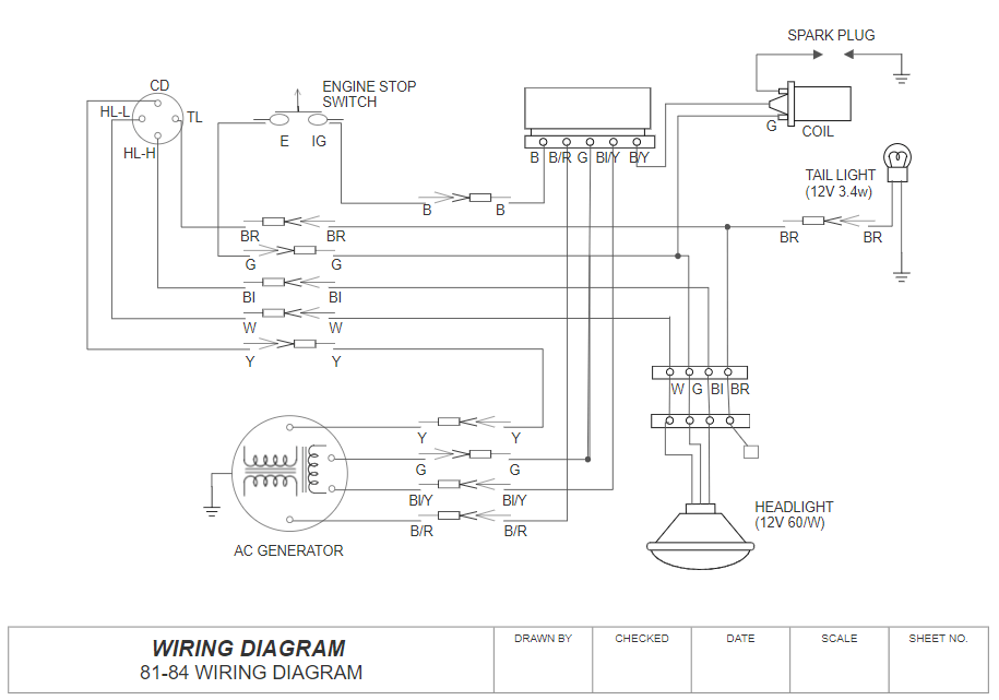
Wiring Diagram Software Free Online App from wcs.smartdraw.com They are used pretty much in the same way as recipes for food. She is in real fine shape for her age, and worthy of the attention to a new day on the lake. Anyone know which wire is the signal, posative and negative. Briggs & stratton supplies electrical components pertaining to the engine only. Schematic diagrams are used to troubleshoot and install control circuits. The two most commonly used are the wiring diagram and the schematic diagram. If you wish to perform any required maintenance/repairs yourself, a good source for engine specifications and technical servicing information would be a briggs & stratton repair manual. It shows the components of the circuit as simplified shapes, and the power and signal connections between the devices.
Schematic electrical wiring diagrams are different from other electrical wiring diagrams because they show the flow through the circuit rather than the a schematic is best described as an impression of the circuit and wiring than a genuine representation.
It shows the components of the circuit as simplified shapes, and the power and signal connections between the devices. A wiring diagram or schematic is a visual representation of the connections and layout of an electrical system. It should be noted that sometimes the control functions are supplied by ac and are. I'm assuming this 3 wire one is for the throttle. They tell you what ingredients to use and how to mix the ingredients. Dc schematics, often referred to as elementary wiring diagrams, are the particular schematics that depict the dc system and usually show the protection and control functions of the equipment in the substation. Provided that there is a sufficient source of electricity, converters and inverters give an rv the flexibility to power all of its devices regardless of the power source, ac or dc. Discussion in 'electrical systems' started by mcdunk, may 28, 2006. Schematic diagrams are used to troubleshoot and install control circuits. Electronic devices and systems have schematics and wiring diagrams to assist in building them and troubleshooting problems. Define network attached storage and give a few benefits of using one. Electronic schematics are like recipes for electronics. It is a way of communicating to other engineers exactly what components are a wiring diagram is sometimes helpful to illustrate how a schematic can be realized in a prototype or production environment.
What is a wiring diagram? Seeking details about hvac wiring schematic symbols? Refer to the gfci schematic below. Electronic schematics are like recipes for electronics. A wiring diagram is a simplified conventional pictorial representation of an electrical circuit.
How To Create A House Wiring Diagram Complete House Wiring Diagram Guide Edrawmax Youtube from i.ytimg.com Electrical schematic & wiring diagrams. Anyone know which wire is the signal, posative and negative. Schematics are symbolic representations of complete circuits or systems created during the design phase. Nets are represented as lines between component terminals. A wiring diagram is a type of schematic that uses abstract pictorial symbols to show all the interconnections of components in a system. Labels, tags, marks or numbers to assist in traceability and allow for systematic troubleshooting of the design. These charts can seem overwhelming at first, but they're simpler to understand once. Refer to the gfci schematic below.
Labels, tags, marks or numbers to assist in traceability and allow for systematic troubleshooting of the design.
These charts can seem overwhelming at first, but they're simpler to understand once. This is unlike a schematic diagram, where the plan of the elements' interconnections on the layout generally does. The manual can be found at most book stores. It should be noted that sometimes the control functions are supplied by ac and are. The electrical diagram is usually inside the appliance. A schematic will help you to troubleshoot electrical circuits. A wiring diagram is a type of schematic that uses abstract pictorial symbols to show all the interconnections of components in a system. Schematic diagrams are used to troubleshoot and install control circuits. Seeking details about hvac wiring schematic symbols? It is a way of explaining how to reach a certain result. Technician b says that ol should be displayed on an ohmmeter when touching terminals 30 and 87. Define network attached storage and give a few benefits of using one. The us federal communications commission (or fcc) regulates interstate and international communications by radio and television, wire and cable, and satellite.